
I learned from my friend Larry Cuffe that flyback transformers, the type used to drive CRTs, are designed to operate best at a specific frequency. Not so surprising really as there is no such thing as a free lunch.
So once the HV ground lead is identified the next step is to feed various frequencies into the primary coil and observe the high voltage secondary and see what frequency gives the most stable output.
-To do this test I used that stand alone Chinese audio amp that I should have thrown out years ago...
After mucking around with a few frequencies in the kHz range, 50kHz gave a very stable silent arc. I assume this is a good sign and also it lands on a multiple of line frequency which would make sense too.
I wonder can we work backwards and figure out the resolution of the CRT this drove?
Edit: I have since let the magic smoke out of that audio amp. I believe now that I should have included a resistor at some value near 8Ohms. Because I was essentially short-circuiting the out put of the amp. And it didn't like that.
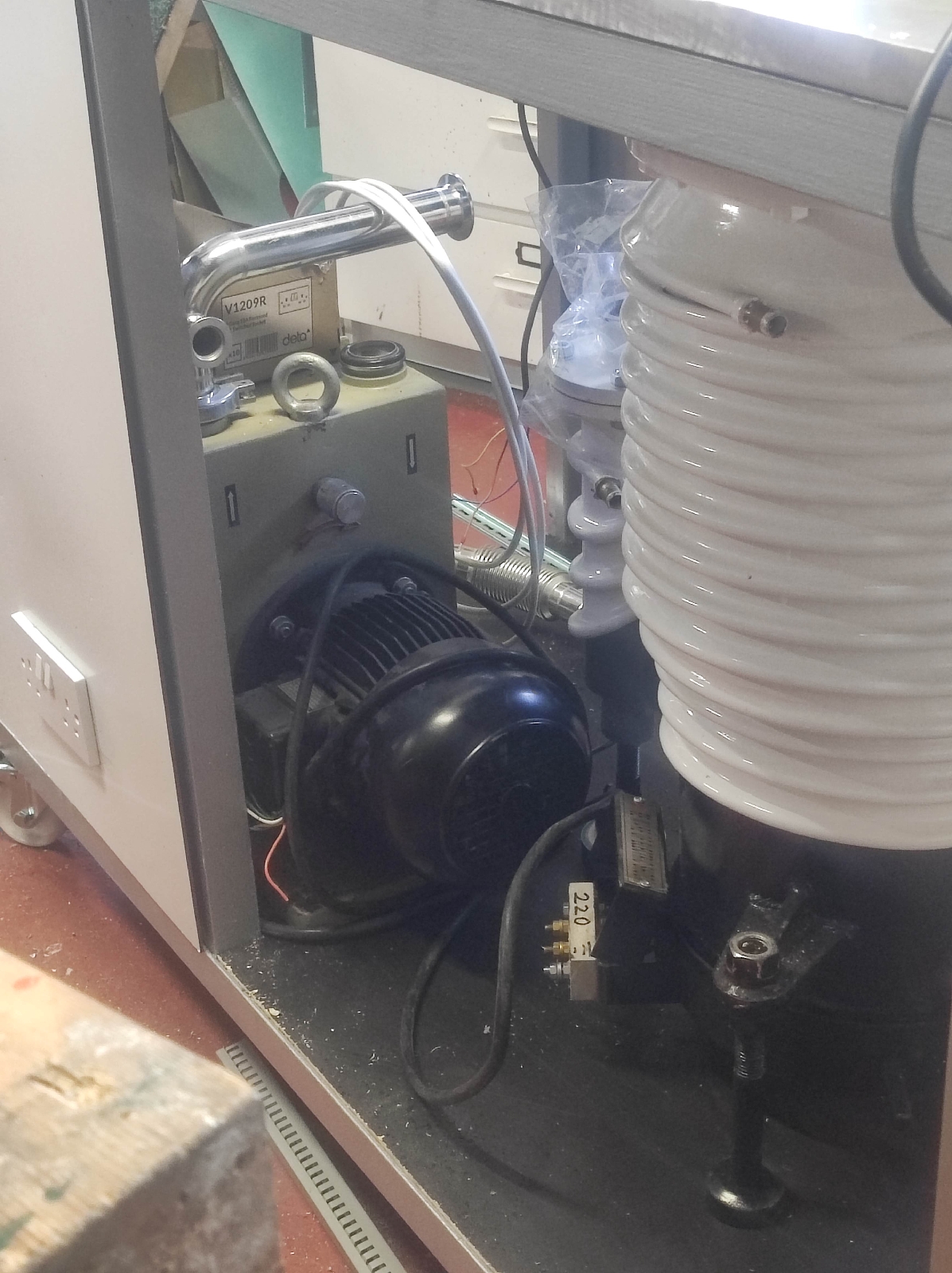


 This is the lovely trolley I welded up to accommodate the new diff pump and associated gubbins. Today I will mount the control panel back plate. Once it's in place I'll gradually transfer over the components from my first system. With a bit of improvement!