Wednesday, November 23, 2011

ZNSE arrival!

The postman brought a great letter today! Inside was a little 1.5mm by15mm ZNSE window with AR coating.

I was very kindly donated this window by Guy at Orcon Technology. Thanks Guy! He sells all sorts of great laser bits on Ebay. Go and visit his Ebay shop:

http://stores.ebay.com/Orcon-Technology


I need to cover the hole in my OC mirror, so this is what I did with it today.

Above you can see the brass mount which holds the OC mirror-
-Its gold on the other side. I cut that mirror from an over head projector mirror. I figured it would be the flattest glass I could get. As any imperfections would be very big when the projector was working. So I guessed they would need to be starting with pretty flat glass to make their mirrors.
That mirror is JB Welded to the brass fitting.
On the left of that pic' is the ZNSE holder. I cut that on my homemade CNC with a 1.6mm single edge cutter. It came out very well. The Window is sitting in a little recess. It should be sitting on an o-ring. But I forgot.

There it is assembled.The pictures are pretty much self explanatory, I think. By the way, I have not tried pump this down yet. And I have not used any grease on the o-rings. I would rather see if I can get away without it. Silicone is a creep.

Tuesday, November 22, 2011

Beginings of a CO2 laser.


I couldn't resist anymore. I've started building a CO2 laser.
Is my new diffusion pump finished? No.
Is my new belljar thing finished? No.
Is my watercooled magnetron finished? No.

To start here is a picture of the laser as it stands today. I will go into construction details as I go along.
From the bottom up!
The base is MDF, to which I have bolted two pieces of Aluminium T-slot stuff I got out of a skip a few years ago.(3* m6 bolts on each side) It was part of an office partition. I unbolted the carpet covered wall sections and was away with the T-slot section!
I was going to use this stuff on the base of the CNC machine but I didn't really have enough, so I stacked it up in the corner!
In this picture there's a lot to see.
First, the brown stuff which the whole laser is mounted to is 'Tufnol' or paper reinforced Bakelite.
This is a very interesting material and the first time I had ever worked with it. It is dense, ridged, machinable and very electrically insulative and very old. Many electrical fittings are still made of it.

If memory serves me air breaks down at 3kv per MM(corrections welcome!)
So I tried to make sure I had at least 15mm between anything conductive near the electrode and T-slot.

Beginings of a CO2 laser.

Where's the interesting stuff?

A bit of a philosophical ramble now.
I am reading a book at the moment which is crystallizing some thoughts I have been having in the last couple of years.
This rant is as much for my own mental organizing as for anybody out there to read!

A false notion which I have believed for ever, consciously and/or subconsciously is that: Great ideas happen because they are great.
Or to be said another way, a brilliant concept must inevitably come to pass due to its high quality alone.

This, I have now decided is all bullshit. Crappy ideas are just as likely to see production.
It all has to do with the structure of their execution.

Why is this?

I have wondered why so many of my own great ideas are gathering dust on shelves in my workshop.
I supposed that ideas got shelved because they turned out to be not such good ideas or became irrelevant for some reason or another.

I now know these are not necessarily the reasons.

In recent years I have been amazed at the fruitfulness of some people. Those works being of varying quality in my eyes but nevertheless work that is completed.

Yet so much of my work lies abandoned.

What words would I use to define a great idea when I have it? Does the list include the words: new, stimulating, exciting.

The question I then asked is: In what way has the idea changed now? Or what is different about the idea now, as compared to when they were first conceived.
What about the idea is missing now, which initially created such energy?

I once put it down to the fact that I am a bit of a perfectionist. I am interested in high quality and workmanship in what I do. And I would always be procrastinating by getting a part or learning new a technique.

The truth is: Creative people get high on NEW ideas.

Ideas generate very positive feelings. It is a natural urge of any creative person to chase those feelings, even be addicted to them. When what we are doing is not getting us high we go back to doing the thing that gives us the buzz!
Thus, once an ideas is concieved and acted on to a greater or lesser extent, the excitment of the new concept fades, and we move on to the next great idea!

So what do we do about that, now that we know?

Cold turkey. Every project will have a comedown. You must expect it and realize what you are experiencing. The idea is still brilliant, it is just old and farmilliar. You must control your wandering eyes and be faithful to it.
This is a battle against your own nature. It is difficult.

Some people are lucky enough to be very self controlled. They can create their own motivation even after the initial high has worn off. For me, that's not the case.

One possible way is-
Impose EXTERNAL motivations which tick my obligation boxes.
Guilt tripping, nagging, promises, deadlines, these make me feel obliged to do things. Deep within myself there is an image of a person of good character which must be protected at all costs. Well there's a motivation.

So follow through is not in the nature of a creative person. So I must be aware that even though I may not be enjoying myself and what I'm doing is not giving me fantastic satisfaction, it may still be the right thing to be doing to get an idea to completion.

So it seems it is not the quality of the idea that is important, it is 'follow through' that is important. And the awareness of when I have reached that phase the idea's life.

Tuesday, November 15, 2011

I was just trying to reply to a comment on the sputtering video and I couldn't get it to work, so this post is a bit personal!

Hi Elena!
To be honest the setup is very low-tech! The magnetron is just a "deep pot" magnet. It needs to be Alnico or Samarium-Cobalt, these do not demagnetize with the heat. The Alnico type are cheaper. So thats what I used. I got it on Ebay.
The silver target is clamped on to the bottom of the magnet by a little ring. When I turn the salad bowl over in the video, you can see the silver disk facing the camera.
I drilled a 6mm hole in the bottom of the salad bowl to hold the magnetron. Its sealed with an o-ring.
The bowl is being evacuated from below the little aluminium "table" in the video. It just blocks the view of where the outlet is!

Oh and don't mind the vacuum gauge, I was just using it as a visual guide for when I had reached the maximum vacuum of my pump/set up. The sensor to read the vacuum level is home made and not the correct one for that meter.

Let me know what bit you are interested in and I'll put up more detailed posts.

Monday, October 31, 2011

One Spoon or Two?

I needed to clean some mercury which I had been given by a classmate of mine in college many years ago. So I googled a bit and came across various methods, many with distillation involved, but then one caught my eye.

SUGAR!

It seemed so simple I gave it a go. In to your dirty metal put some sugar, shake it for 2 minutes and scrape off the dirty sugar.

Add some more and repeat.
And there it was, clean mercury. Now, I can't say how clean, but a huge difference to how it started out.


It had me thinking about the days when making gold was easy and so was going mad with heavy metal poisoning. The Alchemists must have added everything to mercury to see what happened. Perhaps sugar was one thing they tried.
Any ideas whats happening here chemically? Why should the dirt stick to the sugar?

Sunday, September 18, 2011

Sputtering Video

I just uploaded this to YouTube. Click the arrows on the bottom right to watch it full screen.
Lets see if I can get this embed thing to work:

-or-
http://www.youtube.com/watch?v=_aZ16VlN6UI

One thing I didn't mention anywhere there is that the pressure is about 200 microns. And I'm sputtering in air.

Saturday, July 30, 2011

Electroplating a Plastic Doo-da

1. Select your plastic doo-da. I stole this from a child.

2. Glue a piece of copper wire to it. Make sure it well stuck as it will be your handle from now on.I drilled a little hole and glued the wire in.

3. Clean the surface of the plastic thing with Acetone. Warning: You may need to use a less aggressive solvent on some plastics like Styrene or Acrylic. Whatever you use make sure it's a pure solvent that will evaporate without leaving anything behind.
On this head, I scrubbed with a q-tips dipped in Acetone. It's made of PVC, I think.(from this point on you will *not* touch the part to be plated)

4. As paint doesn't like sticking to PVC, I decided to use a plastic primer. This is not necessary on all plastics. The solvents in the spray paints bite into some, like the ones I mentioned above, quite well.

This needs 20 min's to dry before you coat with...5. Zinc Protect. Look at that! 90% Zinc! I did try another zinc 'cold galvanizing' spray which was just glorified decorative silver spray paint. This can is quite heavy. It dries to a very matt grey, which means very little binder. That's good for conductivity.It is important that the zinc spray overlaps from the plastic surface to the copper wire. You can see in the picture it has gone halfway down the wire. Don't forget; no touching the object.

Now clamp it standing up, somewhere warm. And leave it overnight. The solvents must all evaporate out of the paints and they need to cure before the next step. (the less solvent there is, the more the binder shrinks. Therefore the closer the zinc particles are to each other and the more conductive it is.)
That's it next day. Dry and cured.

5. The magic. Get some copper plating solution and decant a bit into a jar.(You should have you gloves and goggles on by now) You can make up your own but commercial solutions have special additives called brighteners in them and it makes a huge difference to the quality of the finish.


I got this bottle from a company in the UK called Balco.
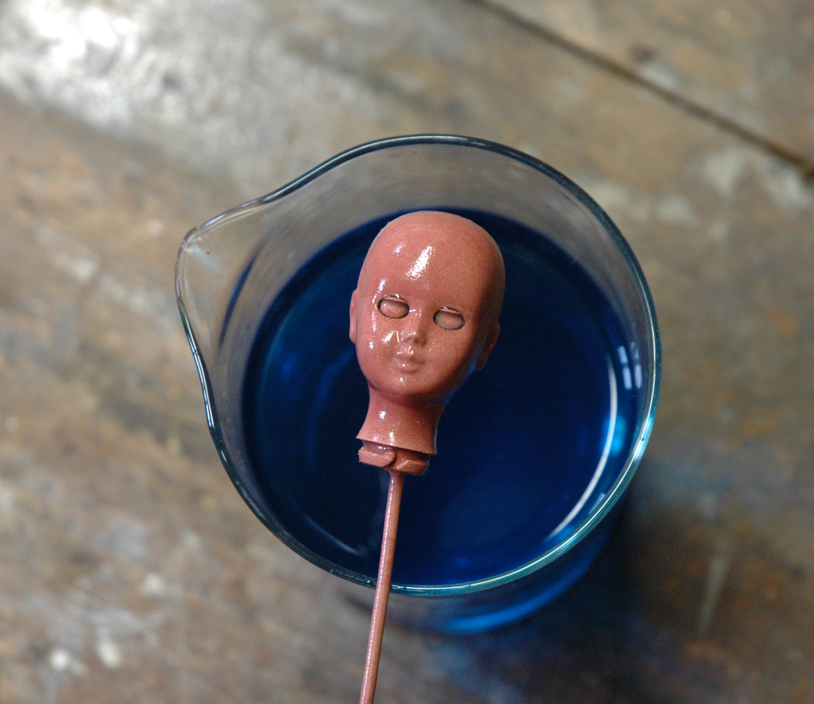
So go a*head* and dip you painted object in...
When it comes out it looks like this! All covered in copper!I find it needs a bit of time to get a good coating. I jiggle it around in the solution for 60 sec or so. Initially it will give off some gas as little bubbles all over it surface.

This is important: 
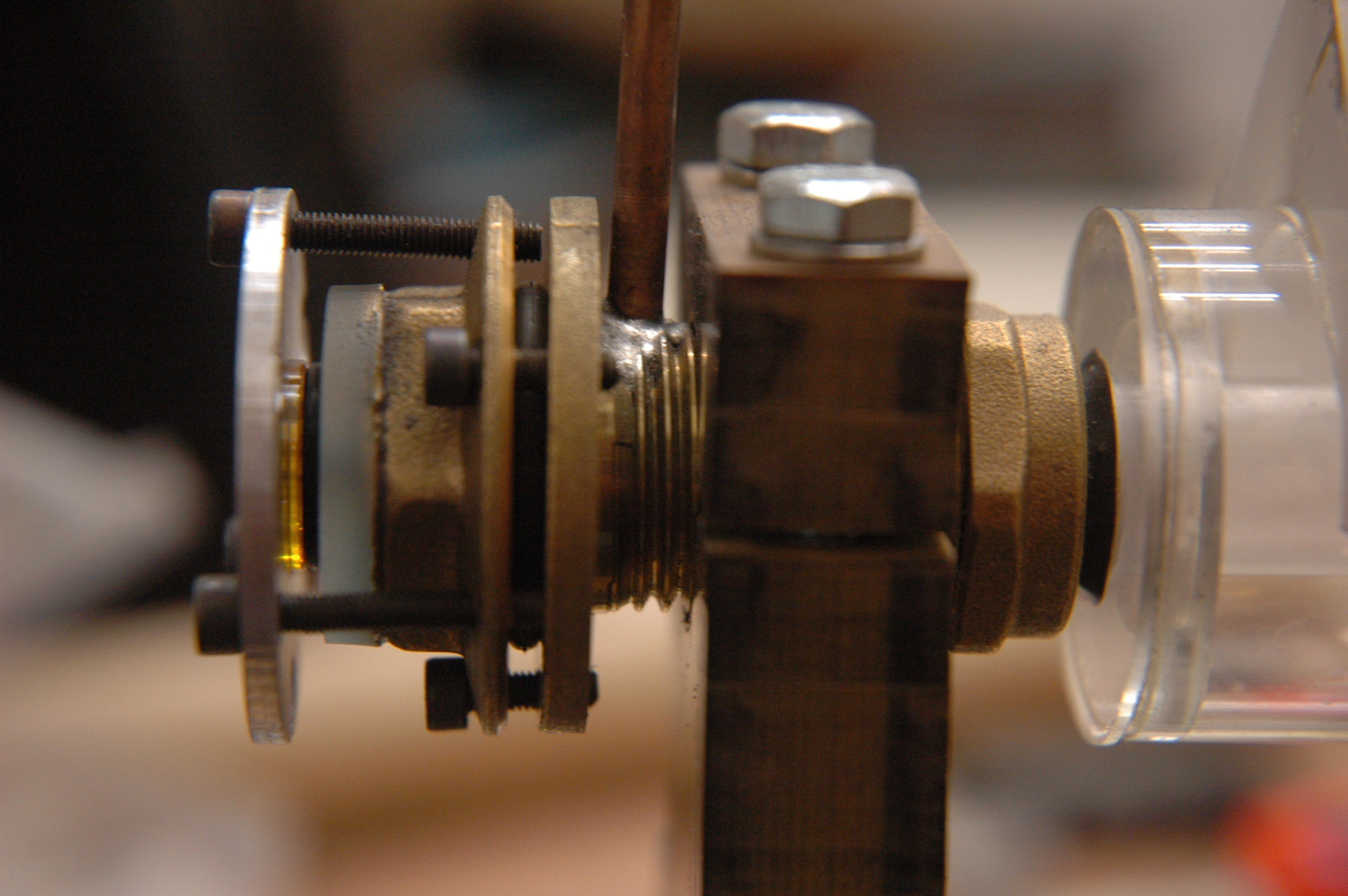
What is happening is the copper in the solution is replacing the surface layer of zinc. The moving of the piece in the solution ensures that the reacted zinc is rinced off the piece allowing the copper to take its place.

6. Now your on to electroplating. This is my set up:
I had to put the vice grips on to weigh the head down because it was floating all the time. Your piece should be submerged so the bare copper wire in just in the solution.
I'm not going to go into how you do electroplating as it is another subject. There is lots of info available on the net and even in books!
Whats important is starting current. As your piece may not be 100% conductive all over you must start plating at a very low current density. That's what they call it "current density".
You can see initially I'm at 100mA. Unfortunately I don't have current control on my cheepo power supply but by voltage seems to work ok.
You'll know if you current density is OK by watching for burning at the wire in the solution. If there is brown gunk developing there drop power by half and watch...
Once you have that minimum level set you can let it plate for a minute or two. Now check it. You may see copper spreading down along the wire over the painted area. Or, on this one, it was plating all over straight away.
Once it is plating all over you can up the current!
The formula is:

Surface in Cm2*0.05= Plating current in Amps

I considered the head to be a cylinder and did a rough estimation from that.
I should note here, it is important to have adequate surface area on your copper electrodes. Twice the surface area you are plating is a good idea.
You can see here I have an electrode at either side of the tank.


Up to 1.8 Amps. I let it plate like that for 2 hours. If you can pump a bit of air through your plating mix it is a good idea. A fish tank airator works well.
I stirred the solution around every few minutes as I checked the progress. Lack of agitation can lead to streaks in the metal being deposited.
You can see the thickness of the metal deposited on the wire. Too thick is not necessary, as this is only a decorative finish.
After a bit of polishing this was the result! I could now burn out the plastic and be left with a hollow copper form.

Friday, July 29, 2011

Critical Backing Pressure

Definition: Maximum backing pressure for a steam jet or vapor vacuum pump to function normally.

This now, I think, has been the major problem with getting my Diff pump working...along with leaks.

I have constructed my pump with a deflector to pump body gap of 5/16" or 4mm.

Not the 2mm as recommended by my ever patient and helpful adviser, Mr. Hart over in the UK. (Who, to his credit, has been consistently correct with his advice over the past few years of my blundering in the world of vacuum. I have always found myself coming around to doing it the way he advised... but only after trying 'my way' first!)


Proceedures in Experimental Physics. J Strong:

The 5/16" clearance between the edge of the umbrella and the condensing wall is not critical, although an optimum exists for any specified set of pressures.

Perhaps 'optimum' should be read as 'maximum' above.


Mr. Hart recounted that he had to heat his homemade diff pump with a blowtorch to get it working the first time. As his electric heater was not doing the trick alone.

www.el-control.dk/katalog/kapitel10.pdf
Page 2:

The critical backing pressure is the highest pressure that a pump can tolerate in the backing line. If the pressure is higher than the critical pressure, the pump may stall. The critical backing pressure depends on:The pump design; the power of the heaters; and the fluid used in the vapor pump.

Now after the disappointment of my homemade diff pump not working, I have new hope of getting some results! I have a Edwards E2M5 on the way.

So the choices to get your pump going are:
-Heat it more.
-Lower backing pressure.
-Or smaller deflector to pump wall distance.

Wednesday, April 20, 2011

CNC mania

At this stage I have the CNC up and running. Not flawlessly mind you!
So I'd better try to catch up with myself!
After getting the supported rails mounted on the machine base, I got going on the gantry.
I put it together roughly first just to get a feel for what it would be like with the weight of the z axis. It moved very easily. A great relief!. My last machine used bronze bushes in place of bearings. They contributed a large amount of friction as far as I could feel. Though my alignments may have been off.
This is the bottom of the gantry sides. I drilled and tapped for M8 bolts.

One point to mention here is that the end you can see was finished on my trusty Aldi router table!

First I cut the Al. plate1mm or so too long. I then made a clamping jig. This consisted of two pieces of flat Al. bar 15mm*5mm or so. These were bolted to each other "squeezing" the plate in between. With a set square it is easy to fix them at 90 degrees.(good enough anyway!)
I used M6 gutter bolts to hold it together.(Low profile heads)
Now, there is a slot in the top of the router table to allow the use of an adjustable angle attachment. This slot was 6mm deep and 15mm wide. In there went the bottom of the clamping jig.
So with a few passes and adjustments, I got my nice square finish which you see above.

This is the Zaxis. The Aluminium I used was from my local friendly scrap dealer. God bless him!

Believe it or not, the12mm Alu plate I'm using came from a bird house! Now that's over engineering!
I think this axis is fairly self explanatory.
The clamp for the router is held in place with 3 M8 bolts.
In this picture I haven't put in the lead screw yet. As it stands I'm just using M8 threaded bar. I
may up grade at some point.

I cut a bit of excess Al. off the to edge of the gantry. To save weight, and to make it "more workman like"!

The top hole here is 20mm and the bottom 22mm(this is to allow adjustability, more on that later). I didn't have a 22mm drill bit so I ended up using the 120 degree V router bit as a drill bit to widen the hole to 22mm! It worked a charm!

*I learned how to drill holes "properly" a few years ago. I would urge anyone to learn the real
method and get them right and accurate every time. It is time consuming, especially if you have loads of holes to drill but it is worth it.*

Measure, scribe, spike point with scribe, centre punch.(double check)
Then: Clamp, align with a pointed tool in drill chuck, replace with centering drill. Drill it. Drill with pilot drill bit (3mm, or so), go ahead with the big bit. Up to 6mm/ or 8mm if your drill press is nice and ridged. Then step up gradually. There's more tricks too!

Here are some bearing blocks:

Monday, February 7, 2011

Slight Blog Departure

After a very busy last few months I'm back to my own work again. This time another project has been pushed to the top of the list due to the fact that I may have a job in a few weeks that needs it finished! So a little departure from hi-vac to CNC router. Again, I'm starting this blog in the middle of the project so I'll just drop you in there!

Quick background: This is Mark III 1/2 of "The Auto-Art Machine".
I started with an MDF one(MkI) which was way too large for my needs so I built a smaller Al. one(MkII). That had an A3 sized cutting area. Much more practical size for my needs. It did, however have some issus with 'play'! I made a few modifications to it with linear bearing on the longest axis and a few other changes. Hence the 1/2 mark. I still wasn't happy with the results.

So onward and upward to MkIII 1/2.
I decided to go with 20mm rails for my X and Y axis. I bought the hardened chromed steel rail. 2m for just under 40 euro, not bad. I got it from Reliance Bearings in Dublin.(Very nice fellas, easy to deal with and helpful. 'Customer service' is a concept many companies in Ireland have yet to grasp! Not Reliance!)

But then I discovered that 20mm dia' rail will sag over my planned 800mm.(In fact, it will sag under its own weight!) So I needed to support it. I found that 1.6m of supported rail would cost 180 euro or more. So I bought 20mm square Al. bar and a 120 degree router bit, and went for it myself!
Thats the bearing that had to go on the rail. I got the bearings on Ebay 30 euro for the 4. The slot in the bottom of the bearing is 12mm but its diagram reads 10mm and standard supported rail systems have a contact of 8mm. So thats what I went for.


I used the 120 degree router bit for the shaping of the supports. I used my cheepo Aldi router table again! Using plenty of cutting oil, I did maybe 14 or 16 passes on each rail. V groove first then the sides. And got this:
I drilled them every 100mm or so to attach the rail. And I learnt that drilling case hardened steel is difficult... Untill you learn the trick! Which took me 10 bad holes. (of 16)
So here is the way I did it:

First, you will need to grind a flat. If you can get all the way through the case hardening at this point all the better. But the thing is, the case hardening was 1.5-2mm thick.
This means that even if the centre of your ground area gets through, the edges did not. Very important. Next mark your centre points with a centre punch. As you are through the hardened steel in the centre it should mark just like mild steel. If not grind a bit more.

Next you will need a tile drill. Choose one with the external diameter of your thread. M6=6mm tile drill. The tip of the bit tapers down to a point so it will only be the case hardened bit which recieves the full 6mm dia., as you will only drill a little way in. The interior of the hole will be ok to continue with a 5mm, normal HSS drill bit to finish the hole. I went in about 15 mm in total. Cutting oil all the way...

Then you can get going with your tap. In theory it will never touch the hardened steel at all. I found the cone shape left by the tile drill led the tap in really well. So the last 6 holes were a dream! I broke a tap very early on, maybe hole 3 or 4, it just touched the hardened steel and snapped right off.
I counter sunk some cheese head m6 bolts and that was that.
A quick note: Aligning all the holes to be square to one another was tricky. What I did was drill and tap the first hole. Screw a nice long piece of threaded bar in and it can be used as a referance to make sure the bar is always rotated to the right angle. You could use a spirit level against the threaded bar. I eyeballed it against the pillar of the drill. That's not a good idea.

This might be a good spot to promote my new portfolio website.