Monday, August 2, 2010

Yet More Leak Testing.

Well the past few days have been filled with leak testing. It has been frustrating. Good silver solder joints going bad. Which means they were not good in the first place!
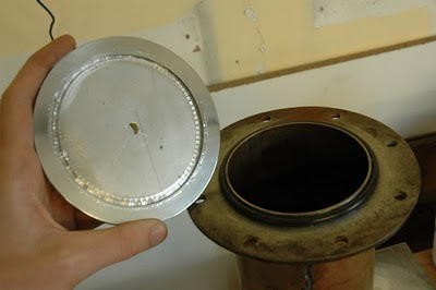
This is my blanking cap for the top of the pump barrel. Its only 6mm thick. That is the thickest I had unfortunately. I cut a groove on the lathe. As you can see it chattered a bit. Its not a big deal because it not the mating surface.

I polished the outside ring where the o-ring would press against. That all worked out well.
You see, the piece of Al. was not big enough to be a flange too, so I used this piece of acrylic as a clamp. The real problem is that the acrylic bend when you start getting near the right compression on the o-ring (20%). This, I found was deforming the cap slightly. Enough to pop the J B Welded brass adapter off.

It held long enough to do the first few tests. I am doing them at 4 Bar.


Initially I had two small leaks. So I fixed them with great enthusiasm and retested. I then found I had four leaks...


This pattern went on for two days till I finally had it sealed. So now I believe my pump is air tight. Vacuum tight? We'll see.

New Pump Interior


After the failure of my two stage chimney design I was convinced to try a single jet instead. Above is a photo of the 2" copper pipe I'm using. Its upside down here. The small holes are for the condenced oil to flow back in to the middle and the larger ones, higher up are for vapor from around the outside to whizz in to the chimney and go up.
Again this is upside down. The skirt in this case is the same diameter as the interior of my pump barrel. This is only a cap over the condensed oil not a down jet deflector.

I cut 5 nicks in the cone with an angle grinder to allow oil to flow back in to the reservoir. The cone here is another stainless steel funnel.

I don't have a pic but the deflector is also one of these funnels. I have an 8mm clearance around the circumference of the cone for the vapor to bridge before it hits the pump wall.
Fingers crossed.

Saturday, July 17, 2010

Nickel Plating


I got a bit of Bright Nickel plating salts from Caswell Europe. I'm using a 'slow cooker' (which I pulled out of a skip) as my plating bath and a pure nickel electrode. This solution likes to be a bit warm in use.

I think the main things about plating successfully are: cleanliness and current control.

My power supply doesn't have current limiting so I have to use the voltage control and just watch the mA meter. Its probably gives a slower deposit or something, but I've had good results with it.
Here is one of my electrodes. I just did them for the fun, I really need to nickel plate the copper parts of the diff pump interior.

I did notice how slippy the surface became after plating. Even to run you fingernail over the surface is quite different to the feel of copper. It must become very flat and smooth at a microscopic level.

The Heater Section.


I found a 220v 600 Watt element from a travel kettle. I saw 4" pumps tended to be around this wattage so I'm hoping it s enough for my homebrew version. The good thing about this element is that it came encased in a lump of aluminium. This allowed a good surface contact between the heater and the bottom of my pump.


Unfortunately, when I soldered the base on to the barrel of the pump it domed very slightly. So the flat heater and the base didn't touch as much as they could. So I decided the best thing to do was grind them against each other.
I had some carbide grits so I used them. I did 80, then 220, then 400 and then Brasso. It took and hour or so. I was quite happy with the result. Not perfect but pretty close.

I needed to isolate the element from its metal box, electrically and thermally. I had kept a few blown plug fuses, thinking they might come in handy some day. Ceramic tubing!
I cut the ends off then emptied out the sand.The underside of the element had a three M3 tapped holes in a nice equilateral triangle. So I measured that and marked it on to the metal box. I drilled that out and put an M3 nut and bolt through the holes.(they were proud about 10mm, just enough to hold the fuses)

I put a bit of high temp silicone on to the end of the bolts and stuck the ceramic tube on.

I screwed short pieces of M3 threaded bar in to the underside of the element and these sat neatly into the tops of the fuses!
As this was going to be squeezed against the underside of the pump, I didn't fix it in permanently.

I had a nice ceramic connector and some high temp wire, from an old halogen security light. So I got the power out of the metal box where it could be connected without fear of melting.

Quick, quick clamp

This is a picture of a temporary clamp I made while I was waiting for the real clamps to arrive. It seemed to work OK. As you can see, its made of two pairs of split rings at 90 degress to each other.

8 m4 bolts are holding them together. I had a short ring of tubing and an o-ring inside.

Note the black marker on the acrylic to make it easier to reassemble. I made this by eye so nothing matched up unless reassembled in the same way it was drilled!

Thursday, July 15, 2010

Leaks, leaks and more leaks


Its a moral tale... and the moral is: pressure test everything as you go along.

I'm guilty of rushing a few bit here in retrospect. I got a bit carried away with the excitement of nearly having the pump finished and didn't pressure it at the silver solder stage. Because once you start soft soldering you cant go back and fix your bad silver solder joints.

So for the pump barrel I pumped the system down as much as I could with the backing pump and painted some shellac on to the area that was leaking. That fixed that for now. How well it stand up to the 220 degress plus, I dont know.
This was in interesting discovery. I found a bad lead solder seam which looked ok and worked ok for the last few months. But now I found it was leaking. Naturally enough it was the last place I looked. I desoldered and resoldered everything else, assuming that one was good. Then in exasperation, I pressure tested it. And there it was...

Today I hooked it all up and pumped a but of water through the cooling sleeve. There was a leak there too. Actually two leaks:

One I thought I'd fixed, close to the bubbles in the top photo.

The other at the top of the sleeve. This one only became apperant when I was pumping the water through. I had tested it initally just with gravity and it was fine. But the small pressure of the pump pushed a bit of water above the inlet level and squirted out the top.

Solution:
High temperature silicone!

Fingers crossed.

Friday, July 9, 2010

The diff' pump video. Looky here.

I've just uplaoded a video to youtube fo the diff' pump as it stands. There are a few posts missing between the last one andthe pump as it is in this video but I'll put the missing info up over the next few days.
In the meantime watch the video! <-- click that!