Saturday, May 23, 2015

ER11 drag engraver

This post is a little off topic so I'm sorry about that. It will be relevant to somebody I suppose.
spring loaded ER11 diamond drag engraver
Above is a spring loaded diamond drag engraver. It's 3mm with a 120 degree angle tip. The issue with it is it needs to be spring loaded to allow for uneven surfaces, but there is very little space to build a mechanism inside an ER11 size collet. The commercial ones work externally to the collet. My thinking was if it is in the collet it would be more ridged and more accurate.
CNC spring loaded diamond engraver
Drag engraver apart
So here it is taken apart. An ER11 collet with a 7mm diameter.
A hard brass pipe(Albion Alloys, metric K +S!)
Polished 6mm steel shaft from an inkjet printer with a spring, I'm not sure where that came from!
I chopped the steel shaft with a hacksaw and stuck it in the lathe. I wrapped the shaft in masking tape to protect it from the jaws of the lathe, then drilled the centre to receive the diamond tip bit and trimmed the other end to take the spring. The spring is squeezed on. This is important for a couple of reasons. It ends up >6mm diameter therefor holding the shaft into the brass tube and so the collet.
That's morealess it. The extra lug at the end is just because I cut the main body of the shaft too short. The grey crap is PTFE/graphite dry lube.
To use...(engineers close your ears), I put it onto the spindle as usual then tighten the nut until the collet pinches the brass tube enough to stop the shaft moving, then loosen the nut a smidge. It should return when pushed in. So I'm using the collet slightly loose...

Thursday, April 2, 2015

The State of Matter as it stands.

DIY metalize
For SEO your supposed to add a caption! DIY Metalization.

A very quick update...this is the state of the system now. The steel belljar is working well. Sight glasses seems to be sealed ok too. After buying a very nicely priced butterfly valve.( Thanks to JF and his wife for the delivery!) I can now cut off the diffstack from the belljar. I got down to below the range of the pirani gauge. Oh yes, I'm sorry I really coped out. I bought a diff pump on Ebay...Interestingly the urge to get the DIY one is still strong in my mind. I do intend to revisit it in the near future. If only to get some closure!
Steel Belljar
Belljar Hoist Mount
 The jar is heavy so I will put it on a pulley and hoist eventually.

Metal Belljar Interior Metalize
Vacuum Chamber Interior
And the interior..stainless steel M10 threaded bars tapped into the base plate.(gas escape grooves cut accross the threads that are in the tapped holes. To try and minimize virtual leaks.). A rolled aluminium ring 5x25mm. Soldered at the join (my first aluminium soldering. Very possible. Probably not a good idea for sealing... Must fly!

Friday, June 6, 2014

A big jar of nothing.

 There it is with the view ports welded in. I went for one to view filament and on to view object being coated. (I didn't do the welding, I thought, as it was critical I leave it to the expert!)

 There was some distortion when the welding happened so I had to sand the flanges flat again. I made that little sanding thing to help. It took a while but I got then flat enough for the o-rings to take up any of the remaining irregularity.

 
 The strangest thing was the bottom of the jar was no longer flat after the welding process. It shrank upwards towards the welded pipe. I was very surprised. It was across a section of at least 50mm. I spotted it when I did a test pump down and the bottom gasket was buzzing as air rushed in through the gap! Back to the counter top with sand paper as described before.

 Above is a view of the o-ring seal on view port. The o-ring are viton(€16 each woops). 6mm cross section. The glass is a square in 12mm, normal type. I just got a glazier to cut it for me.
So the tube sits proud of the flange by about 3mm. This keeps the o-ring in place. I cut the clamping rings from 3mm aluminium. Drilled the top one tapped the underside one. It is split as you can see from the side view.
Oh and I pumped it down today, its tight! Yipee!


Tuesday, April 8, 2014

Cheapo (metal) Bell Jar the beginnings...

After a long stretch of solid work I got a chance to get back to vacuum for a while.
I was getting a bit nervous of my glass belljar imploding so I decided to go for a metal one instead.
After seeing a guy on youtube who built a mildsteel box to coat telescope mirrors in I decided to give the gas cylinder a second try.
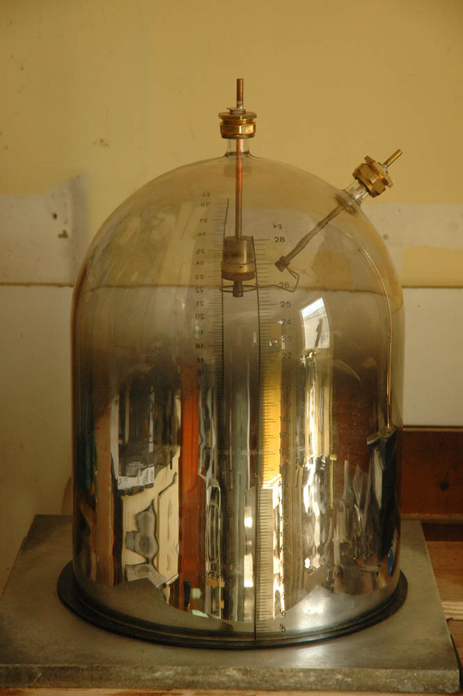
I bought a used gas cylinder 380mm diameter just right for my base plate at 400mm.
I let the remaining gas out and unscrewed the valve. Don't forget to fill it with water to displace the remaining gas before you go a cuttin'

 
I marked the line by wrapping a yoga at around the cylinder to get a parallel line. That wasnt a good idea... you need to use some thing not so stretchy, that defeats the purpose! I marked away and used the bottom end with the complete dome.
I put the cylinder on it side and cut it with the water still inside. It was pouring out all over the place. I trimmed much of the foot ring off too. I wanted to get rid of excess weight. It is heavy.
Once it was cut I dried it straight away. We don't want any rust forming, very bad for outgassing.
Then on to leveling. Even though I paid great attention to the cutting I still spent 3 hours leveling the cut to get it nice ond flat. For this process I spray glued strips of al'oxide paper to a scrap of countertop. Its nice and flat and very ridged. I did a couple of hours of 80grit and an hour with 120...
Very tiring on the arms! During the sanding I regularly ran a black marker along the edge so I could see my progress clearly. I would watch the colour sand off, and the black patches get smaller and smaller. Eventually I got down to a consistant edge. I went then, by hand with a finer sand paper to get rid of the 120 scratches. I rubbed along the edge insted of across it. If there are scratches left they are better not to be radial across the edge as it is more likely to leak in that case.

The whole interior had a dark crust on it. I don't know what it is, possibly passivated with phosphate? I diligentlly sanded this away. There was still a bad smell coming from the tank. This got less and less as the crustyness came off.
I cut a new flat rubber gasket and greased up and sure enough it pumped down to 40micron the limit of my pump....

Thursday, July 25, 2013

A Little Closer!

This is the casating I wanted to try a bit of evaporation on to. Its made of fastcast polyurethane and then spray-painted with gloss black.As the Al coating has no filling qualities the gloss of the coating is a result of the texture of the base.
I picked up a few aluminium prefused tungesten filiments from a company called Midwest Tungsten in the US of A. This is a bit overkill for a DIYer but the were cheap, from their surplus bin!

 
So I hung the plastic part from a wire inside the bell and began to pump down...
When I got to 40micron or so I turned on the MOT power supply.(I wrote this up in the blog a good while ago)
After 20 seconds I got this! I was delighted! Just mechanical pump, no diff. Now, its not up to scratch yet but these little victories help me keep the faith.(Ignore the electrodes poking through, they are just sealing the holes here)
A strange thing at this vacuum is the fact that the back of the part got a covering of Al. as well. It must fly around in the belljar at these crappy vacuum levels.
 There is the front. Opaque but not bright. It has greyness in person. Getting there...

Monday, June 10, 2013

I found a leak!

After a long absence from my metalisation project I decided to get back to it. I was having a real nightmare with my belljar not getting the vacuum level I was expecting. Or that I needed to even start a diff pump. There were so may potential leaks I was overwhelmed for a while. So I decided to go step by step and eliminate the possibilities starting at the pump.
Flexible pipe tested fine, under water with compressed air. The second section however had a f**king leak. Right there, bubble, bubble, bubble. I couldn't believe it. The solder joint looked fine but it was leaking.
So I Glyptaled it under a vacuum and I was all fixed up!
More to follow...

Wednesday, November 14, 2012

Copper bellows again


I decided I wasn't going to let the peskey bellows defeat me, so I went for it again. My copper bellows MkII are a success! Here's what I did...

As before, I made a wax model on the lathe. This time I stuck to the rules I mentioned in my other copper bellows effort above.
So my recesses are tapered and wider than they are deep.
Wired, dipped in white/mineral spirits, covered with graphite powder. After a bit, burnished with a Qtip with more graphite on it.
Copper plated at very low current.
Below is the bellows just out of the plating solution.
It had two sessions in the plating solution. One to get the form strong enought to survive a bit of handeling and the burn-out. And another to build up a decent thickness of metal. 

Another warning note here: I was calculating on the assumption that the solution was putting down 1 micron every 2.5mins, as I read in the literature.

But even after 6/7 hours I only ended up with 150 microns or so. Measured from the waste I cut out of the top of the form. I'm sure the vertical parts of the cylinder are thicker but the important flexing parts are only that thick, if not less. I would like to have gotten .3mm or even more. As there is serious strength,brittleness and porosity issues with simple electroforming like this.

I realised later that the problem was that even though I had calculated my current density ok, I was using voltage control to achieve it. So my overall power/wattage was less than it should be. Hence the thin deposit.